<body><script type="text/javascript"> function setAttributeOnload(object, attribute, val) { if(window.addEventListener) { window.addEventListener('load', function(){ object[attribute] = val; }, false); } else { window.attachEvent('onload', function(){ object[attribute] = val; }); } } </script> <div id="navbar-iframe-container"></div> <script type="text/javascript" src="https://apis.google.com/js/platform.js"></script> <script type="text/javascript"> gapi.load("gapi.iframes:gapi.iframes.style.bubble", function() { if (gapi.iframes && gapi.iframes.getContext) { gapi.iframes.getContext().openChild({ url: 'https://www.blogger.com/navbar.g?targetBlogID\x3d15270625\x26blogName\x3dAeroHydro+Blog\x26publishMode\x3dPUBLISH_MODE_BLOGSPOT\x26navbarType\x3dBLUE\x26layoutType\x3dCLASSIC\x26searchRoot\x3dhttps://aerohydroblog.blogspot.com/search\x26blogLocale\x3den_US\x26v\x3d2\x26homepageUrl\x3dhttps://aerohydroblog.blogspot.com/\x26vt\x3d-8891551275759441737', where: document.getElementById("navbar-iframe-container"), id: "navbar-iframe" }); } }); </script>
AeroHydro  

  AeroHydro Blog
 
   MultiSurf and SurfaceWork - Marine and Industrial Design - Software and Services


Posts

Importing Images for Sketch Planes
Representing Weights
Points and curves in a plane
Component tips from Reinhard Siegel and Robert Page
Promotion
Welcome to the AeroHydro weblog
 
     Archives
August 2005
May 2010
June 2010
 
     Links
AeroHydro Home
Site Feed

Importing Images for Sketch Planes

Image Import

You have an image of a boat you would like to emulate in MultiSurf. Maybe you have images for Profile, Plan, and Body and want to use them as reference in MultiSurf. Follow along and this should go a long way towards getting you started.
First you have the 3 views, which should be cropped to their minimum extents. We are going to map these images to surfaces in MultiSurf. If the image is cropped to the extent of the frame, we will know the exact dimension of the image in MultiSurf, because we know the dimension of the surface which is the host. Change the surface size and the image sales with the surface.


Here examples to the 3 views of a vessel we are interested in modeling.

The next item on the list is to start an new model in MultiSurf. The fist item of business is to prepare the model to accept Texture mapping. A Texture attribute needs to be registered in the model file and we do this with a command. Open the command line interface by pressing the keyboard shortcut "w" and typing the command: "registerattribute Texture 0" (without quotations).

Next we need to prepare our images so MultiSurf will accept them. They need to be Bitmaps and the number of pixels in each direction (H and W) need to be a power of 2. (2, 4, 16, 64, 512, 1024 as examples)

Here is our Plan view with dimensions 256 X 64:


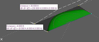
Next we want to create the surface to receive our first image and we'll start with the Plan view. Create a surface with the leading dimensions of the starboard side of the vessel. In our case we have a surface on the *Z=0 plane which is 30' long and 4' wide. It is a B-Spline surface with 4 corner points as parents as seen in the next image.


The image (above) we want to map on to this surface is saved in the same folder as our model and named 'plan_1.bmp. To map it to the surface we use another command. Select the surface and type "Setattribute Texture "plan_1.bmp"". The quotes go around the image name, but not the command itself. Here are the results:

It looks good but the bow is pointed in the wrong direction and the the centerline does not line up along the X axis. This can be fixed by editing the surfaces to change its orientation. The next image shows the orientation marks along with the corrected mapping of the image.

The image looks quite a bit different than the sleek plan view of the original, but remember, we can edit the dimension of the surface and the mapped image will update


The next series of images will show the other views, Body and Profile.
Importing Images for Sketch Planes - Friday, June 11, 2010 -

Representing Weights

Representing weights

You can represent weights of as-yet-undetailed items in Tools/Weight Schedule. Create points with weight attributes to stand in for the missing items; for example, a point named 'ballast' with a unit weight of 4800-kg to represent a ballast casting. Place it where you expect the center of gravity of the ballast to be. It will be included in the weight schedule and combined with other weights. Later, when you've created geometry for the ballast and assigned it unit weights, you can delete the point, or change its unit weight to 0.
If the model has symmetry, be sure to make this point Symmetry Exempt, or you keel could be twice as heavy and might sink the boat when you open Hydro.

Representing Weights - Wednesday, June 02, 2010 -

Points and curves in a plane


Creating a sketch plane in MultiSurf

In the image at the left the aft two master curves are in frames which allow them to be set at different angles by editing the Roll, Pitch, or Yaw angles of the Frame.

The points have their Dragging constraint set so they can only be dragged in the Y or Z direction, effectively locking them into the YZ plane of the frame.The procedure below gives you some steps to complete this construction.

Create a Frame from three points or a Roll/Pitch/Yaw Frame from one point and use this as a "sketching plane".
Put points in the frame and be sure to make the Frame the parent of the points. The points should be located in the x-y, x-z, or y-z planes of the frame. Depending on the plane in which the points are located, make the appropriate dragging constraint for all the points. This way the points can not be dragged off that plane with the mouse. Most kinds of curves will lie in a plane when all their control points do (Arcs, BCurves, CCurves, Lines, FCurves...)
You can hide the construction entities when the curve is done.

Labels:

Points and curves in a plane - Tuesday, May 25, 2010 -

Component tips from Reinhard Siegel and Robert Page

We are undergoing an improvement on how components are used and handled in the MultiSurf model. Here are some comments Reinhard Siegel offered upon seeing the development effort and he also adds valuable tips on how he manages components now. I have interspersed some tips of my own in his text.

> When I look through my library of components, there are hatches, doors,
windows, winches, blocks, fairleads, traveller, mast, boom, rigging wires,
stanchions, etc. Their common property is: an assembly of objects, that
depend on one single base point. Thus when loaded into a model, the only
parent for the component is a point entity (insertion point ip_xxx).
Dragging that ip moves all the entities that were in the component "xxx". To
access those entities conveniently I make entity lists:

> 1) an entity list "View_xxx", that holds the final, presentable objects to
show
2) an entity list "Edit_xxx" with "handles" or "grips", that allow
modification: winch meridian shape, stanchion height and diameter, hatch,
window, door dimensions etc.

RP - This entity list is a convenient way to form the content of a custom Real Values Dialog (RVD) for editing the component. The Entity List above should contain only Variables or Formulas so it will yield a RVD when the Entity List is selected.


> So by the "View_xxx" entity list the component can easily selected via the
Entity manager for hide, show or save actions (for example a Pov-Ray file).
Selecting the point "ip_xxx" and all its children is the road to remove the
entities created via component from the model.
>
> Of course, entity lists like "View_xxx" and "Edit_xxx" are not restricted to
objects created in a model via Component Load. I use them extensively to tie
a group of things together for fast selection - show, hide, save.

So far to my practice. And I must admit, it has been working fine for me.

Reinhard has seen the Development version and is commenting on same...
>
> And now there is a Component heading in the EM. Can it be an improvement?
Can it help to make the construction of a model easier to understand, easier
to edit? Similar to procedures and modules in a program code?


When experimenting with the component "entity" I thought: this smaller tree
of only the contributing entities is good - less objects, all in one part of
the tree, thus more clearness, easier to understand, easier to adopt to
specific requests.
>
>
So I agree with your proposal to list component entities only under its
component heading. I much agree with your idea to indicate the parents of
the component (display in red). I strongly suggest to make them inactive,
that is, selectable, but not further expandable. So the user has a clear
indication of their function - the link between the group of entities and
the main model body.
>
> When talking to users about components, it soon comes to the question: can I
show/hide them with a click? They have in mind a subset of the entities in
the component, the presentable or final entities. They consider the
component merely as an assembly of finished surfaces, that needs to be shown
or hidden.

RP - Yes, this development build will be available for for inspection very soon.
>
> If we look at a component as a separate entity, could it have (beside its
other properties) the property "Visible Entities"? Then Show/ Hide could
refer to this list.


> So far for now. I do hope, this lines are of help to you and the MultiSurf
development team. Much progress.

With kind regards,

Reinhard


Component tips from Reinhard Siegel and Robert Page - Wednesday, May 19, 2010 -

Promotion

We have a promotion underway. Learn more here.
Promotion - Tuesday, August 09, 2005 -

Welcome to the AeroHydro weblog

Welcome to the AeroHydro weblog. I'll be posting news, tips and hints. Feel free to leave a comment.

Cheers-
-Michael Shook
AeroHydro, Inc.
Welcome to the AeroHydro weblog - -


AeroHydro Home

© 2005 AeroHydro, Inc.